Programming 101
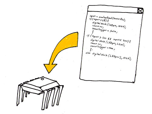
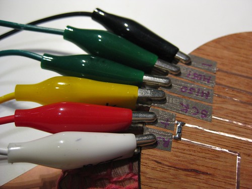
David Mellis has posted some great tutorials on how to turn an Arduino board into an ISP programmer and use it to program bare microcontrollers such as the ATtiny85.
Getting started with AVR programming >> http://hlt.media.mit.edu/wiki/pmwiki.php?n=Main.AVRProgramming
Advanced AVR programming >> http://hlt.media.mit.edu/wiki/pmwiki.php?n=Main.AVRProgrammingAdvanced
From Arduino to a Microcontroller on a Breadboard >> http://arduino.cc/en/Tutorial/ArduinoToBreadboard
Using FabISP and Arduino IDE for programming ATtiny45 and 85s – NOTES TO SELF!
Edit the boards.txt file in the Arduino application folder!
>> http://fab.cba.mit.edu/content/projects/fabkit/
>> http://fab.cba.mit.edu/classes/MIT/863.09/people/mellis/fabisp/index.html
>> http://fab.cba.mit.edu/content/projects/fabisp/
>> http://fab.cba.mit.edu/content/tools/microcontrollers/compiling.html
>> http://hlt.media.mit.edu/wiki/pmwiki.php?n=Main.ArduinoATtiny4585
forum answer >> http://arduino.cc/forum/index.php/topic,70841.0.html
Improving sound code for ATtiny45 and 85
To make your sound quality better, change register for clock speed of tiny85 by typing the following into your terminal.
If you are using the MKII programmer:
avrdude -p t85 -c avrispmkii -P usb -U lfuse:w:0xe2:m
If you are using Dave’s fab isp progammer:
avrdude -p t85 -c usbtiny -U lfuse:w:0xe2:m
Also see this fuse calculator website to see where we got the settings from:
>> http://www.engbedded.com/fusecalc/
After setting the fuses, upload the following code to your microcontroller:
// using leah buechley’s sound code, taken from: http://web.media.mit.edu/~leah/LilyPad/07_sound_code.html
int sensorPin = 2;
int speakerPin = 3;
int LED0 = 0;
int LED1 = 1;
int LED2 = 2;
int reading;
int count = 0;
int threshold = 850;
int LEDstate = 0;
int SENSORstate = 0;
int previousSENSORstate = 0;
int SENSORgo = 0;
void setup()
{
pinMode(sensorPin, INPUT);
digitalWrite(4, HIGH);//sensorPin
pinMode(speakerPin, OUTPUT);
pinMode(LED0, OUTPUT);
pinMode(LED1, OUTPUT);
pinMode(LED2, OUTPUT);
digitalWrite(LED0, HIGH);
digitalWrite(LED1, HIGH);
digitalWrite(LED2, HIGH);
}
void loop() {
reading = analogRead(sensorPin);
SENSORstate = reading/(threshold/8);
if(SENSORstate == previousSENSORstate) SENSORgo = 0;
else SENSORgo = 1;
if(SENSORstate == 0 && SENSORgo == 1) scale(‘C’);
if(SENSORstate == 1 && SENSORgo == 1) scale(‘D’);
if(SENSORstate == 2 && SENSORgo == 1) scale(‘E’);
if(SENSORstate == 3 && SENSORgo == 1) scale(‘F’);
if(SENSORstate == 4 && SENSORgo == 1) scale(‘G’);
if(SENSORstate == 5 && SENSORgo == 1) scale(‘A’);
if(SENSORstate == 6 && SENSORgo == 1) scale(‘B’);
if(SENSORstate == 7 && SENSORgo == 1) scale(‘H’);
previousSENSORstate = SENSORstate;
if(reading < threshold && LEDstate == 0){
count++;
LEDstate=1;
}
if(count == 1 && LEDstate == 1) {
digitalWrite(LED0, HIGH);
digitalWrite(LED1, LOW);
digitalWrite(LED2, LOW);
}
if(count == 2 && LEDstate == 1) {
digitalWrite(LED0, LOW);
digitalWrite(LED1, HIGH);
digitalWrite(LED2, LOW);
}
if(count == 3 && LEDstate == 1) {
digitalWrite(LED0, LOW);
digitalWrite(LED1, LOW);
digitalWrite(LED2, HIGH);
}
if(count == 4 && LEDstate == 1) {
digitalWrite(LED0, HIGH);
digitalWrite(LED1, HIGH);
digitalWrite(LED2, HIGH);
}
if(count > 4) count = 1;
if(reading > threshold) LEDstate = 0;
}
void scale (char note)
{
if(note == ‘C’)
beep(speakerPin,2093,500); //C: play the note C (C7 from the chart linked to above) for 500ms
if(note == ‘D’)
beep(speakerPin,2349,500); //D
if(note == ‘E’)
beep(speakerPin,2637,500); //E
if(note == ‘F’)
beep(speakerPin,2793,500); //F
if(note == ‘G’)
beep(speakerPin,3136,500); //G
if(note == ‘A’)
beep(speakerPin,3520,500); //A
if(note == ‘B’)
beep(speakerPin,3951,500); //B
if(note == ‘H’)
beep(speakerPin,4186,500); //C
}
void beep (unsigned char speakerPin, int frequencyInHertz, long timeInMilliseconds) // the sound producing function In order to visualize certain sensor data you might want to visually graph serial data. At the very bottom of this interview with Tom Igoe you’ll find Arduino and Processing code necessairy for such a graph: The following link also contains both Arduino and Processing (as well as Max/MSP) code for a graph:
{
int x;
long delayAmount = (long)(1000000/frequencyInHertz);
long loopTime = (long)((timeInMilliseconds*1000)/(delayAmount*2));
for (x=0;xVisualizing sensor data
>> http://wiki.processing.org/w/Tom_Igoe_Interview
>> http://www.arduino.cc/en/Tutorial/Graph


Leave a Reply